
How Ultrasonic Welding, Laser Welding, and Mechanical Connections Influence Battery Performance, Safety, and Reliability
Introduction: Battery Manufacturing Is Fundamentally About Reliable Electrical Connections
When discussing lithium-ion battery performance, attention usually focuses on energy density, discharge rate, cycle life, and safety.
However, another important factor is often overlooked:
The quality of electrical connections throughout the battery system.
From thin electrode current collectors to cell terminals, module interconnections, and high-current battery busbars, every connection contributes to the electrical and mechanical integrity of the finished battery.
A battery may contain excellent cells, but poorly designed or manufactured electrical connections can still compromise its performance.
High contact resistance can cause localized heating. Weak joints may deteriorate under vibration. Welding defects can increase electrical losses or create potential safety hazards.
For high-power applications such as electric vehicles, industrial robots, and heavy-lift UAVs, these risks become particularly important.
The challenge is that battery manufacturing involves different materials, thicknesses, and joint configurations.
A welding process suitable for joining multiple layers of thin copper foil may not be appropriate for connecting a thick aluminum busbar.
Likewise, the process used to seal a prismatic cell enclosure differs from the method used to connect pouch-cell tabs.
This is why battery manufacturing relies on multiple joining technologies.
Two particularly important methods are:
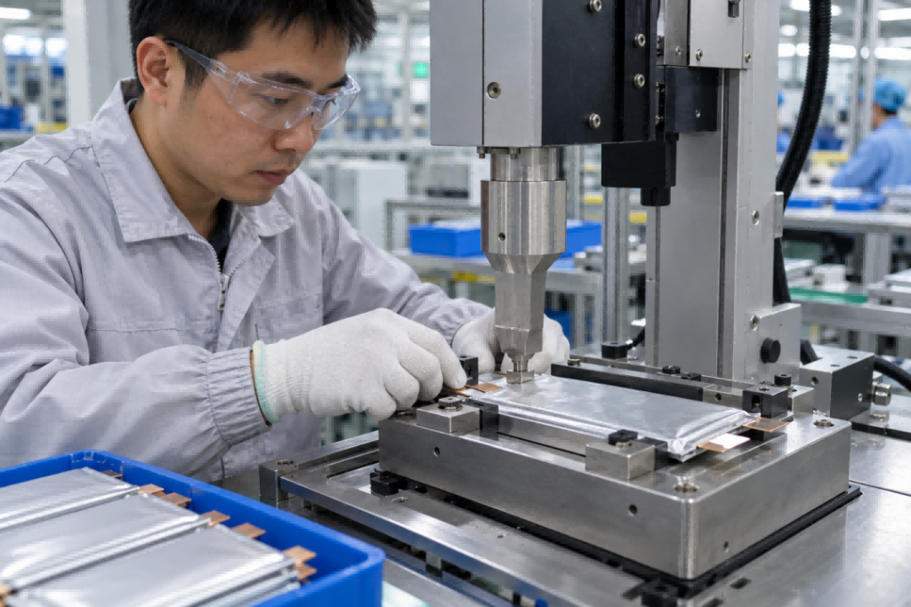
Ultrasonic Metal Welding — commonly used for thin, multilayer metallic connections.
Laser Welding — widely used for precision metallic joining, including many cell-terminal, enclosure, and busbar applications.
Mechanical fastening and other joining methods also remain important, particularly at the module and PACK levels.
Understanding where each technology belongs helps engineers make better decisions about battery reliability, manufacturing quality, and system integration.

1. Electrode and Tab Welding: Why Ultrasonic Metal Welding Is Widely Used
The first major joining challenge appears inside the battery cell.
Lithium-ion electrodes typically consist of active material coatings applied to thin metallic current collectors.
For many conventional lithium-ion cells:
- The negative electrode uses copper foil.
- The positive electrode uses aluminum foil.
During cell assembly, multiple current-collector layers must be connected to the corresponding tab or current-collection structure.
These materials are thin and can be sensitive to excessive heat or mechanical damage.
1.1 How Ultrasonic Metal Welding Works
Ultrasonic metal welding is a solid-state joining process.
It uses high-frequency mechanical vibration together with applied pressure to form a metallic bond.
Industrial systems commonly operate at ultrasonic frequencies such as 20–40 kHz, depending on the equipment and application.
During welding, the combined action of vibration and pressure disrupts surface films and promotes intimate metallic contact and bonding.
Unlike conventional fusion welding, ultrasonic welding does not require bulk melting of the joined metals.
This makes it particularly useful for joining thin metallic foils.
1.2 Why It Is Suitable for Multilayer Current Collectors
Battery electrode assemblies may contain many layers of copper or aluminum foil.
A suitable welding process must create reliable electrical continuity without excessively damaging the thin materials.
Ultrasonic welding offers several advantages:
- Relatively low overall thermal input
- Ability to join multiple thin metallic layers
- Short processing times
- Compatibility with common current-collector materials
- Potential for repeatable automated production
These characteristics make it an established joining method in battery manufacturing.
1.3 Typical Material Combinations
Common examples include:
Negative electrode:
Multilayer copper foil → Copper tab or current-collection component
Positive electrode:
Multilayer aluminum foil → Aluminum tab or current-collection component
The exact joint design depends on the cell architecture.
1.4 Common Welding Defects
Although ultrasonic welding avoids bulk melting, it can still produce defects.
Potential problems include:
- Foil tearing
- Incomplete bonding
- Excessive foil thinning
- Mechanical damage
- Electrode coating damage
- Poor electrical continuity
Excessive welding energy or pressure can damage thin materials.
Insufficient welding energy may produce a weak joint.
1.5 Critical Process Parameters
Important variables include:
- Ultrasonic amplitude
- Welding force
- Welding time or energy
- Tool geometry
- Surface condition
- Layer alignment
Proper contact between the metallic layers is essential.
1.6 Quality Inspection
Manufacturers may use several inspection methods:
- CCD-based visual inspection
- Peel or tensile testing
- Electrical resistance measurement
- Cross-sectional examination
- Process-signal monitoring
No single test provides a complete assessment of every possible defect.
A robust quality-control strategy combines suitable inspection methods with validated process parameters.
2. Laser Welding in Cell Manufacturing
After current-collector connections are established, other joining operations may require a different process.
For many prismatic and cylindrical cell designs, laser welding plays an important role.
Laser welding uses concentrated optical energy to create localized melting and solidification.
It can produce narrow welds with precise positioning and is well suited to automated production.
2.1 Tab-to-Terminal and Adapter Connections
In some cell architectures, current-collector assemblies connect to an adapter plate or terminal structure.
Laser welding may be used for these connections, depending on material compatibility and joint design.
The process can provide:
- Localized energy delivery
- High positioning accuracy
- Repeatable automated welding
- Suitable joining of selected metallic components
However, laser welding parameters must be carefully controlled.
2.2 Prismatic Cell Enclosure Welding
Rigid prismatic cells often use metallic enclosures.
The cell housing and top cover must be joined to create a reliable seal.
Laser welding is widely used for certain enclosure-sealing operations.
These joints are important because they influence:
- Cell sealing integrity
- Resistance to electrolyte leakage
- Mechanical durability
- Manufacturing consistency
2.3 Electrolyte Filling-Port Sealing
Following electrolyte filling and the relevant manufacturing processes, some rigid-cell designs use a welded sealing component.
Laser welding may be used to close the filling port.
The weld must provide reliable sealing without introducing unacceptable defects.
2.4 Why This Differs From Pouch-Cell Manufacturing
Pouch lithium-ion batteries use flexible laminated packaging rather than a rigid metal can.
Their package edges are generally sealed using a controlled heat-sealing process.
Therefore, the statement that battery enclosure sealing is performed by laser welding does not apply universally.
Rigid prismatic cell sealing and pouch-cell package sealing are fundamentally different manufacturing operations.
This distinction is especially relevant to industrial UAV batteries, where pouch cells are commonly used.
3. Laser Welding Defects: Why Precision Does Not Eliminate Risk
Laser welding is precise, but its high local energy density creates its own manufacturing challenges.
3.1 Porosity
Gas trapped during solidification can form pores within the weld.
Porosity may reduce joint strength or affect sealing performance.
3.2 Cracking
Some materials and joint configurations are susceptible to solidification cracking or other weld-related cracking mechanisms.
3.3 Spatter
Molten metal droplets may be ejected from the welding region.
Spatter is particularly concerning when it creates conductive debris near sensitive battery components.
If metallic particles enter a cell or remain in an electrically sensitive location, they may contribute to insulation failures or internal short-circuit risks.
3.4 Incomplete Fusion
Insufficient energy or poor joint fit-up may result in incomplete bonding.
A weld may appear acceptable externally while failing to provide adequate mechanical strength or electrical conductivity.
3.5 Excessive Penetration
Excessive laser energy can damage nearby components or create unwanted melting.
This is particularly important near thin battery components.
3.6 Important Process Controls
Manufacturers may control:
- Laser power
- Welding speed
- Beam positioning
- Focus
- Shielding gas
- Joint fit-up
- Surface cleanliness
- Weld trajectory
The appropriate parameter window depends on the material and joint geometry.
3.7 Quality Verification
Relevant inspection methods may include:
- Visual inspection
- Weld geometry measurement
- Mechanical strength testing
- Electrical resistance testing
- Leak testing for sealed enclosures
- Metallographic examination
- Suitable nondestructive inspection
For cell sealing, leak testing is especially important.
For electrical connections, resistance and mechanical integrity are critical.
4. Module Assembly: Connecting Individual Cells
Once cells are manufactured, they must be connected into the required electrical configuration.
A battery module may contain cells connected in series, parallel, or both.
The connection method depends on:
- Cell format
- Terminal material
- Current requirements
- Mechanical design
- Production volume
- Serviceability requirements
Common joining methods may include:
- Laser welding
- Resistance spot welding
- Ultrasonic welding
- Mechanical fastening
The correct choice depends on the specific battery architecture.
4.1 Nickel and Nickel-Plated Connections
Nickel strips and nickel-plated steel connections are commonly encountered in certain cylindrical-cell battery assemblies.
Depending on the design, these connections may be joined through resistance spot welding or other suitable methods.
Laser welding may also be used in selected applications.
However, it would be inaccurate to assume that all nickel-strip connections are laser welded.
4.2 Nickel-Copper Composite Connections
Nickel-copper composite structures can combine different electrical and joining characteristics.
Copper provides high electrical conductivity, while nickel-containing surfaces may improve compatibility with certain joining processes.
The suitability of the connection depends on its actual construction and welding method.
4.3 Aluminum Terminal Connections
Some battery modules use aluminum terminals or aluminum interconnects.
Laser welding may be appropriate for selected aluminum-to-aluminum connections.
However, the process must account for surface oxides, heat input, and joint geometry.
5. Hidden Welding Defects: Why Electrical Resistance Matters
One of the most serious risks in battery-module assembly is a connection that appears acceptable but has poor electrical performance.
An incomplete or weak weld may initially pass a basic visual inspection.
However, under high-current operation, its electrical resistance may cause excessive heating.
The relationship is:
P = I²R
Where:
- P = Resistive power loss
- I = Current
- R = Electrical resistance
This equation explains why small resistance increases can become important in high-power battery systems.
Example: A High-Current Battery Connection
Consider a battery connection carrying 100 A.
If its resistance is 0.2 mΩ:
P = 100² × 0.0002 = 2 W
If the connection resistance increases to 1.0 mΩ:
P = 100² × 0.001 = 10 W
The electrical loss increases fivefold.
This heat may be concentrated in a relatively small connection area.
The resulting temperature depends on heat dissipation, connection geometry, and operating duration.
For a high-discharge battery pack, connection resistance is therefore not merely an efficiency issue.
It can become a reliability and safety concern.
Why Visual Inspection Alone Is Insufficient
A weld can look acceptable while having:
- Incomplete bonding
- Internal voids
- Poor electrical continuity
- Insufficient effective contact area
Electrical resistance measurement and mechanical testing can provide additional evidence of joint quality.
For critical connections, manufacturers should establish validated acceptance criteria.
6. PACK-Level Busbars: Connecting Modules and Distributing High Current
At the PACK level, electrical connections become larger and may carry substantial current.
Busbars are used to distribute electrical power between cells, modules, protection devices, and external terminals.
Common busbar materials include:
- Copper
- Aluminum
- Copper-aluminum composite structures
The joining method depends on the system architecture.
6.1 Laser-Welded Busbars
Laser welding is used in some battery PACK designs.
It can provide compact and repeatable joints where the materials and geometry are suitable.
6.2 Bolted Busbar Connections
Mechanical fastening is also widely used.
Bolted connections are particularly important where components require assembly access, maintenance, or replacement.
For example, main busbars may connect to:
- Battery disconnect units
- Contactors
- Fuses
- Power-distribution assemblies
- External electrical terminals
A bolted connection must be designed to maintain appropriate contact pressure and low electrical resistance.
6.3 Riveted Connections
Some designs use riveted connections.
Their suitability depends on mechanical requirements, electrical performance, and manufacturing strategy.
6.4 Why Not Weld Everything?
Welding may provide compact permanent connections, but permanent joints are not always desirable.
Bolted connections can offer:
- Easier assembly
- Serviceability
- Component replacement
- Compatibility with certain high-current structures
However, bolted joints also require appropriate torque control, contact-surface preparation, and protection against loosening.
At the PACK level, the best connection is not necessarily the one with the strongest weld. It is the one that meets electrical, mechanical, thermal, manufacturing, and service requirements.
7. Copper-Aluminum Welding: One of the Most Difficult Battery Joining Challenges
Copper and aluminum are widely used in battery systems because of their electrical conductivity and weight characteristics.
However, joining them can be challenging.
7.1 Different Material Properties
Copper and aluminum differ in:
- Melting temperature
- Thermal conductivity
- Optical absorption characteristics
- Thermal expansion behavior
- Metallurgical compatibility
These differences influence laser welding behavior.
7.2 Intermetallic Compound Formation
During copper-aluminum fusion joining, brittle intermetallic compounds may form.
Excessive formation of these phases can reduce joint toughness and mechanical reliability.
7.3 Process Optimization
Engineers may use carefully controlled welding parameters and joint designs to manage the interface.
Important considerations include:
- Heat input
- Material positioning
- Surface preparation
- Weld penetration
- Interface composition
- Cooling behavior
7.4 Alternative Joining Strategies
Depending on the application, engineers may consider:
- Ultrasonic joining
- Resistance-based joining
- Specialized laser processes
- Transition materials
- Copper-aluminum composite components
- Mechanical connections
The goal is to obtain acceptable electrical conductivity and mechanical reliability without introducing excessive metallurgical risk.
8. Ultrasonic Welding vs. Laser Welding: A Practical Comparison
Both processes are important in battery manufacturing, but they solve different joining problems.
ParameterUltrasonic Metal WeldingLaser WeldingJoining principleSolid-state bondingLocalized fusion weldingMain energy sourceHigh-frequency mechanical vibrationConcentrated laser energyBulk meltingGenerally not requiredUsually involvedTypical strengthsMultilayer thin foilsPrecision metallic joints and selected thicker componentsCommon applicationsCurrent-collector foil and tab joiningCell terminals, rigid-cell sealing, selected interconnects and busbarsMain risksFoil tearing, weak bonding, tool-related damageSpatter, porosity, cracking, incomplete fusionImportant controlsAmplitude, force, time, tool geometryPower, speed, focus, shielding, fit-upTypical inspectionsMechanical tests, visual inspection, resistanceVisual inspection, resistance, mechanical tests, leak tests where relevant
The Engineering Principle
Ultrasonic welding is particularly valuable when thin metallic layers must be joined with limited bulk heating.
Laser welding is particularly valuable when precise localized fusion is suitable for the materials and joint geometry.
Neither process is universally superior.
The best choice depends on the connection requirements.
9. What Makes Welding Different for UAV Pouch LiPo Batteries?
Industrial UAV batteries introduce a different set of design priorities from automotive battery systems.
UAV battery packs often emphasize:
- High discharge capability
- Low weight
- Compact packaging
- Reliable electrical connections
- Vibration resistance
- Stable performance under demanding operating conditions
Pouch cells are frequently used because their flexible form factor supports different pack configurations.
However, pouch battery assembly requires careful attention to tab connections.
9.1 Pouch-Cell Tab Connections
Pouch cells typically have external metallic tabs.
These tabs may be aluminum, copper, nickel-containing, or composite structures, depending on cell design.
The selected joining process must account for:
- Tab material
- Tab thickness
- Current requirement
- Thermal sensitivity
- Mechanical loading
- Connection geometry
Ultrasonic welding, laser welding, resistance welding, or other appropriate methods may be considered depending on the application.
9.2 Why High Discharge Current Changes the Requirements
High-current UAV applications place greater demands on every electrical connection.
A connection with excessive resistance can cause localized heating.
This may increase energy losses and accelerate degradation of nearby materials.
Therefore, UAV battery-pack engineering must consider both the cells and their interconnections.
9.3 Weight Optimization vs. Connection Reliability
Reducing conductor thickness may lower battery-pack weight.
However, thinner conductors can increase electrical resistance or reduce mechanical robustness.
The design must balance:
- Electrical conductivity
- Mechanical strength
- Thermal performance
- Weight
- Manufacturing consistency
9.4 Vibration and Repeated Handling
Industrial UAV batteries may experience repeated installation, removal, transport, and vibration.
Electrical joints must remain reliable under the intended mechanical conditions.
For this reason, static electrical resistance alone is not sufficient to establish long-term reliability.
Appropriate mechanical and environmental validation is also important.
10. Why Weld Quality Matters for UAV Endurance and Flight Reliability
Battery performance is often discussed in terms of cell specifications.
For example:
- Nominal voltage
- Capacity
- Energy density
- Maximum discharge current
- Internal resistance
However, the complete battery pack includes additional electrical resistance from:
- Cell tabs
- Welded connections
- Busbars
- Wires
- Connectors
- Protection devices
These contributions affect total voltage drop and heat generation.
10.1 Voltage Drop Under Load
The approximate voltage drop across a connection is:
ΔV = I × R
At high current, even small connection resistance can create a measurable voltage drop.
10.2 Electrical Efficiency
Energy dissipated as heat is energy that cannot be delivered to the aircraft’s propulsion system.
However, the actual effect on flight endurance depends on the complete power system and mission profile.
10.3 Localized Heating
Excessive heat near a connection may affect insulation, adjacent components, and long-term reliability.
10.4 Mechanical Failure
A connection that weakens under vibration or thermal cycling may create intermittent electrical behavior.
For an aircraft, intermittent power delivery can have serious consequences.
In UAV battery engineering, connection reliability is part of flight reliability.
11. Battery Welding Quality Control: What Should Manufacturers Measure?
A reliable welding process requires more than choosing the correct equipment.
Manufacturers must establish a controlled production and inspection process.
11.1 Incoming Material Control
Material consistency affects weld quality.
Relevant characteristics include:
- Material composition
- Thickness
- Surface condition
- Coating quality
- Dimensional tolerances
11.2 Process Parameter Control
Important parameters should be monitored and maintained within validated ranges.
For ultrasonic welding, these may include amplitude, force, energy, and time.
For laser welding, they may include power, speed, focus, and weld positioning.
11.3 Visual Inspection
CCD systems can help identify visible defects such as:
- Misalignment
- Surface damage
- Excessive spatter
- Missing welds
- Certain geometry defects
However, visual inspection cannot identify every internal defect.
11.4 Mechanical Testing
Peel, tensile, or other appropriate tests can help evaluate joint strength.
The selected method must match the joint geometry.
11.5 Electrical Resistance Testing
Resistance testing is particularly important for current-carrying joints.
The measurement method must provide adequate sensitivity for low-resistance connections.
11.6 Nondestructive Testing
Depending on joint design and production requirements, additional inspection methods may be appropriate.
Examples include selected ultrasonic, optical, or other nondestructive techniques.
11.7 Reliability Validation
For demanding applications, testing may also include:
- Thermal cycling
- Vibration
- Repeated current loading
- Mechanical fatigue
- Environmental exposure
These tests help evaluate whether the connection remains reliable throughout its intended service life.
12. How UAV OEMs Should Evaluate Battery-Pack Connection Quality
For UAV manufacturers, the quality of battery-pack connections should be part of supplier evaluation.
Useful questions include:
1. Which joining methods are used?
Understand whether the pack uses ultrasonic welding, laser welding, resistance welding, or mechanical connections.
2. Are the joining methods appropriate for the materials?
Copper, aluminum, nickel, and composite materials have different joining characteristics.
3. How is connection resistance controlled?
Ask how critical electrical connections are evaluated.
4. How are hidden defects identified?
Visual inspection alone may be insufficient.
5. Has the pack been tested under realistic discharge conditions?
High-current operation can reveal thermal problems that are not obvious at low current.
6. How is vibration resistance validated?
This is particularly relevant to UAV applications.
7. Are the welding and assembly processes consistent?
Repeatability matters as much as the performance of an individual sample.
8. How are failures traced and investigated?
Manufacturing records and suitable inspection data can support root-cause analysis.
These questions can help UAV engineers assess whether a battery pack is suitable for long-term operational use.
13. The Future of Battery Joining Technology
Battery joining technology continues to evolve as cell designs and manufacturing requirements change.
Several development directions are particularly important.
13.1 Advanced Laser Processes
Improved laser sources, beam control, and process monitoring may expand the range of suitable battery connections.
13.2 New Current-Collector Architectures
Emerging cylindrical and other cell designs may require different approaches to current collection and terminal joining.
13.3 Improved Dissimilar-Metal Joining
Copper-aluminum connections remain an important area for process development.
13.4 Automated Quality Monitoring
Manufacturers are increasingly interested in monitoring welding conditions and detecting abnormal process behavior.
13.5 Lightweight High-Current Interconnections
For UAVs and other weight-sensitive applications, engineers must continue improving the balance between conductivity, weight, and reliability.
The long-term objective is not simply to weld faster.
It is to produce electrical connections that remain reliable throughout the battery system’s intended operating life.
Conclusion: The Best Battery Cells Still Need Reliable Electrical Connections
Battery manufacturing involves a series of electrical joining challenges.
Each stage requires an appropriate technology.
At the electrode level, ultrasonic metal welding is widely used for joining thin multilayer current collectors.
At the cell level, laser welding is important for many terminal and rigid-enclosure applications.
At the module level, manufacturers may use laser welding, resistance welding, ultrasonic welding, or other suitable methods.
At the PACK level, welded, bolted, and riveted connections may all have appropriate roles.
The correct choice depends on materials, geometry, electrical requirements, mechanical loads, and manufacturing conditions.
For industrial UAV batteries, the importance of connection quality is particularly clear.
High discharge currents increase the consequences of electrical resistance.
Vibration and repeated handling create mechanical reliability requirements.
Weight limitations place additional constraints on conductor and connection design.
A high-performance UAV battery therefore requires more than high-quality cells.
It requires reliable electrical connections throughout the entire power path.
Battery performance begins with cell chemistry. Battery reliability depends on how the entire system is engineered and connected.
UniquePower | UAV Battery & Charging Solutions
We support industrial UAV manufacturers and system integrators with battery cell selection, customized battery packs, BMS integration, and charging solutions.
Website: www.uniquepower.net Email: sales@uniquepower.net WhatsApp: +86 178 2175 0340
#BatteryManufacturing #BatteryWelding #UltrasonicWelding #LaserWelding #BatteryPackDesign #UAVBattery #LithiumIonBattery #BatteryEngineering