
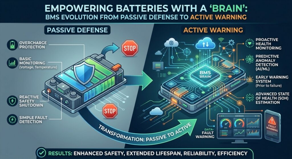
From cell-level voltage monitoring and thermal protection to early fault detection, AI diagnostics, and flight-controller integration
Introduction: What Happens Before a Drone Battery Fails?
Imagine an industrial drone battery developing a small internal defect.
The battery may continue operating normally for days or weeks. During charging and discharging, however, subtle changes begin to appear.
One cell group exhibits unusual voltage behavior. Its self-discharge rate increases. A localized region becomes warmer than expected.
Depending on the failure mechanism, the cell may also begin generating decomposition gases.
None of these signs necessarily means thermal runaway is imminent. But together, they may indicate that the battery is no longer behaving normally.
The challenge is detecting these abnormalities before they develop into a serious safety event.
This is where a Smart Battery Management System (Smart BMS) becomes essential.
For industrial UAVs, the BMS is much more than a circuit board that prevents overcharging.
It is part of an integrated safety system responsible for monitoring battery conditions, identifying abnormal behavior, communicating with the aircraft, and initiating appropriate protective actions.
However, UAV battery safety introduces a complication that does not exist in the same way for stationary battery systems:
Disconnecting a battery during flight may protect the battery while simultaneously endangering the aircraft.
This is why UAV battery protection must be considered at both cell level and aircraft level.
In this article, we will examine how smart BMS technology can improve the safety and reliability of pouch LiPo batteries used in industrial drones.
1. Passive Safety vs. Active Safety in UAV Pouch Batteries
Battery safety begins long before a BMS detects a fault.
The cell chemistry, electrode design, separator, electrolyte, manufacturing quality, and pack structure all influence the probability and consequences of battery failure.
These elements form the foundation of passive battery safety.
Examples include:
- Stable electrode materials
- Reliable separators
- Controlled manufacturing processes
- Electrical insulation
- Mechanical protection
- Thermal barriers
- Appropriate cell spacing and enclosure design
Passive safety reduces the likelihood of certain failures and helps limit their consequences.
Active battery safety, by contrast, relies on monitoring, diagnostics, control, and protective actions.
A smart BMS may perform functions such as:
- Individual cell-voltage monitoring
- Current monitoring
- Temperature measurement
- Overcharge and overdischarge protection
- Overcurrent and short-circuit protection
- Cell balancing
- State-of-charge estimation
- State-of-health estimation
- Fault detection and event logging
- Communication with the UAV flight controller
These two approaches are complementary.
A BMS cannot reverse a severe internal short circuit that has already triggered self-sustaining thermal reactions.
Likewise, a well-designed battery enclosure cannot compensate for inadequate charging protection or poor electrical monitoring.
Reliable UAV battery safety requires both passive protection and active monitoring.
2. The Three Fundamental Safety Boundaries: Voltage, Current, and Temperature
The foundation of BMS protection is maintaining battery operation within an acceptable electrical and thermal range.
For pouch LiPo batteries, three parameters are especially important:
Voltage, current, and temperature.
Each parameter is directly connected to electrochemical degradation and potential failure mechanisms.
2.1 Overcharge Protection: Preventing Lithium Plating and Cathode Instability
Overcharging a lithium-ion pouch cell can initiate several damaging processes.
Depending on cell chemistry and operating conditions, excessive charging may cause:
- Excessive lithium extraction from the cathode
- Reduced cathode structural stability
- Electrolyte oxidation
- Metallic lithium plating on the anode
- Gas generation
- Increased internal heat generation
In severe cases, these mechanisms can contribute to internal short circuits and thermal runaway.
A smart BMS should therefore monitor individual series-cell voltages rather than relying exclusively on total battery voltage.
Consider a 12S UAV battery.
Even if the total pack voltage appears acceptable, one cell group may already be approaching its maximum permitted voltage.
The BMS must identify that individual cell before overcharging occurs.
A typical protection strategy combines a voltage threshold, confirmation time, and hysteresis.
Hysteresis prevents repeated switching when the measured voltage fluctuates near the protection threshold.
The correct voltage limits depend on the specific cell chemistry and manufacturer specifications.
2.2 Overdischarge Protection: Preventing Irreversible Cell Damage
Overdischarge can also damage lithium-ion cells.
Under sufficiently severe conditions, copper current-collector dissolution may occur, potentially contributing to copper deposition and internal short-circuit risks during subsequent charging.
For industrial UAV batteries, overdischarge protection must also consider high-current voltage sag.
During takeoff, climbing, or aggressive maneuvering, a pouch battery may experience a temporary voltage drop caused by internal resistance.
The relationship can be approximated as:
V_terminal ≈ V_OCV − I × R_internal
Where:
- V_terminal is the battery terminal voltage.
- V_OCV is the open-circuit voltage.
- I is the discharge current.
- R_internal is the effective internal resistance.
A temporary voltage drop under high load does not necessarily mean the cell has reached its true end-of-discharge condition.
However, repeatedly operating near the lower voltage limit can accelerate degradation.
This creates an important design challenge.
The BMS must distinguish normal high-load voltage sag from dangerous undervoltage conditions.
For UAV applications, protection thresholds and response logic should be validated under realistic flight-current profiles.
2.3 Current Protection: High Discharge Capability Requires Coordinated Control
Industrial UAV pouch batteries may operate at substantial discharge currents.
Heavy-lift multirotors, agricultural drones, and other high-power platforms can demand particularly high current during takeoff and climbing.
Excessive current may cause:
- Increased resistive heating
- Connector overheating
- Conductor or busbar damage
- Accelerated cell aging
- Excessive voltage sag
The approximate resistive heating relationship is:
P_loss = I²R
This means heating increases with the square of current when resistance is held constant.
For example, doubling current increases resistive power loss by approximately four times.
A smart BMS may monitor current and identify overload conditions.
However, the response must account for aircraft propulsion requirements.
A sudden current interruption during flight can be more dangerous than a controlled reduction in available power.
Therefore, UAV protection design should distinguish between conditions requiring immediate electrical isolation and conditions where coordinated flight-level mitigation is appropriate.
3. Temperature Monitoring: Why Sensor Placement Matters
Temperature is one of the most important indicators of battery operating condition.
Most conventional battery packs use NTC thermistors to monitor temperature.
But the effectiveness of temperature protection depends on more than sensor accuracy.
3.1 Surface Temperature Is Not Internal Temperature
Pouch cells generate heat internally during charging and discharging.
The temperature inside the cell may differ from the temperature measured at its surface.
This difference becomes especially important during high-current operation.
A sensor mounted on the outside of a cell may respond later than an internal hotspot develops.
Therefore, a BMS that relies only on a single temperature measurement may fail to represent the most critical thermal conditions.
3.2 Multiple Temperature Sensors Improve Observability
For multi-cell UAV battery packs, temperature sensors should be positioned according to the expected thermal distribution.
Potential monitoring locations include:
- Regions with high current density
- Areas near electrical connections
- Cells with limited cooling
- Locations where heat may accumulate
The number of sensors depends on battery configuration, size, and risk assessment.
More sensors do not automatically guarantee better protection.
Their placement and interpretation are equally important.
3.3 Temperature Rise Rate: Detecting Abnormal Heating Earlier
Absolute temperature is only one part of thermal monitoring.
The rate of temperature change, commonly expressed as dT/dt, can provide additional diagnostic information.
A battery operating at a moderate temperature but experiencing an unusually rapid temperature rise may require investigation.
For example:
High current + Expected temperature increase
may represent normal operation.
Moderate current + Unexplained rapid temperature increase
may indicate abnormal internal heating.
A more advanced BMS can evaluate:
- Absolute temperature
- Temperature-rise rate
- Temperature differences between cells
- Current history
- Ambient conditions
This approach can provide better diagnostic information than a single fixed temperature threshold.
However, temperature-rise limits must be validated for the actual cell and pack design.
There is no universal dT/dt threshold that reliably predicts thermal runaway in every pouch LiPo battery.
4. Cell Balancing: Why the Weakest Cell Determines Pack Performance
A UAV battery pack consists of multiple cells connected in series, parallel, or both.
Even cells from the same production batch may exhibit small differences in:
- Capacity
- Internal resistance
- Self-discharge rate
- Temperature response
- Aging characteristics
Over time, these differences can increase.
In a series-connected battery, the cell group with the lowest usable capacity may reach its voltage limit before the others.
During charging, one group may reach the upper voltage threshold first.
During discharging, another may reach the lower threshold first.
This is the weakest-link effect.
4.1 Passive Balancing
Passive balancing dissipates excess energy from higher-voltage cells through resistive elements.
Its main advantages are relatively simple circuitry and lower cost.
Its limitations include energy loss as heat and limited balancing current.
4.2 Active Balancing
Active balancing transfers energy between cells or cell groups.
It may offer higher balancing efficiency and faster correction under certain conditions.
However, it also introduces greater circuit complexity and cost.
4.3 What Matters for UAV Batteries?
For high-power UAV applications, balancing must be evaluated alongside weight, electrical efficiency, reliability, and operating requirements.
An active balancing circuit is not automatically superior for every UAV battery.
A well-designed passive balancing system may be appropriate for some configurations.
The important question is whether the balancing strategy can maintain acceptable cell consistency throughout the battery’s intended service life.
Balancing improves cell consistency, but it cannot repair a damaged or severely degraded cell.
5. Early Thermal Runaway Warning: Listening to Voltage, Temperature, and Gas
Basic protection systems respond when monitored values exceed predefined limits.
Early warning systems attempt to recognize abnormal behavior before a severe failure develops.
Thermal runaway can involve a sequence of electrochemical and thermal reactions.
Depending on the initiating mechanism, measurable abnormalities may develop before major venting, smoke, or fire.
However, the available warning time varies significantly.
Some defects evolve gradually.
Others progress rapidly with little opportunity for intervention.
Therefore, no BMS should be assumed capable of predicting every thermal runaway event.
5.1 Voltage Abnormalities and Self-Discharge
A developing internal short circuit may cause increased self-discharge.
Under suitable conditions, this may appear as an abnormal voltage decline during rest.
A smart monitoring system can compare the behavior of individual cell groups over time.
Potential indicators include:
- Unusual voltage relaxation
- Increasing self-discharge
- Abnormal differences between cell groups
- Sudden voltage collapse
The difficulty is distinguishing genuine defects from normal changes caused by temperature, state of charge, and aging.
Long-term trend analysis may provide more useful information than isolated measurements.
5.2 Temperature Abnormalities
Unexpected temperature increases may indicate excessive internal heat generation.
A multi-parameter algorithm can compare temperature behavior with current and recent operating history.
For example, a cell that becomes warmer than neighboring cells under similar conditions may warrant closer monitoring.
5.3 Gas Detection: A Potential Chemical Early Warning
Battery degradation and thermal abuse can generate gases such as:
- Hydrogen (H₂)
- Carbon monoxide (CO)
- Carbon dioxide (CO₂)
- Hydrocarbons
- Volatile organic compounds
Depending on cell chemistry and failure conditions, gas release may occur before a large external temperature increase.
Gas sensors can therefore provide an additional diagnostic channel.
However, gas detection presents several engineering challenges.
The signal depends on:
- Gas composition
- Cell venting behavior
- Sensor location
- Enclosure ventilation
- Sensor response time
- Background contamination
Gas detection is not guaranteed to precede voltage or temperature abnormalities.
Its effectiveness must be demonstrated for the relevant battery system.
5.4 Is Gas Detection Practical for UAV Pouch Batteries?
This question is particularly important.
Industrial UAV batteries face strict mass and volume limitations.
Adding gas sensors, sampling channels, and associated electronics increases system complexity.
Furthermore, many UAV battery packs are not sealed enclosures.
Gas may escape or become diluted before reaching a sensor.
For some large battery systems, gas sensing may provide valuable additional information.
For compact UAV battery packs, high-quality voltage and temperature monitoring may offer a more practical balance of cost, weight, and diagnostic capability.
The correct approach depends on the aircraft’s risk profile.
Multi-sensor monitoring is valuable, but every additional sensor must justify its mass, power consumption, complexity, and reliability.
6. From Basic Protection to Intelligent Fault Diagnosis
Traditional BMS designs often rely on fixed thresholds.
For example:
- Maximum cell voltage
- Minimum cell voltage
- Maximum current
- Maximum temperature
These protection mechanisms remain essential.
However, they primarily evaluate present operating conditions.
More advanced diagnostic systems can also analyze historical behavior.
6.1 State of Health Estimation
State of Health (SOH) describes battery condition relative to a defined reference state.
SOH estimation may consider:
- Capacity degradation
- Internal resistance growth
- Cycle history
- Temperature exposure
- Charging behavior
For commercial UAV operators, improved SOH estimation can support battery maintenance and replacement decisions.
6.2 Internal Short-Circuit Detection
Advanced algorithms may analyze small changes in self-discharge, voltage relaxation, and thermal response.
The objective is to identify abnormal behavior that fixed thresholds may not detect.
However, internal short-circuit detection remains technically challenging.
Reliable diagnosis requires accurate measurements and representative validation data.
6.3 Remaining Useful Life Prediction
Remaining Useful Life (RUL) estimation attempts to predict how long a battery can continue meeting a defined performance requirement.
For a UAV fleet, this may support:
- Battery replacement planning
- Maintenance scheduling
- Fleet availability management
- Battery rotation strategies
Predictions should include uncertainty rather than presenting an exact future failure cycle as a certainty.
7. AI-Based BMS: From Reactive Protection to Predictive Safety
Artificial intelligence can potentially improve battery diagnostics by identifying patterns across large datasets.
For example, an AI model may analyze:
- Voltage trends
- Current profiles
- Temperature history
- Cell imbalance
- Charging behavior
- Internal resistance evolution
It may identify deviations associated with accelerated degradation or abnormal operation.
However, AI does not automatically make a BMS safer.
Its effectiveness depends on:
- Sensor accuracy
- Data quality
- Training-data coverage
- Model validation
- Computational reliability
- False-alarm performance
For UAV applications, false alarms can have significant operational consequences.
A diagnostic model that repeatedly triggers unnecessary emergency landings may reduce mission reliability.
Conversely, a model that misses a developing fault may fail to provide useful protection.
Therefore, AI-based diagnostics should complement well-validated conventional protection functions.
Predictive intelligence is valuable only when its decisions are reliable enough for the intended application.
8. Digital Twins: Simulating Battery Behavior Before Real-World Failure
A digital twin is a virtual representation of a physical system that uses models and relevant data to simulate its behavior.
For UAV batteries, a digital twin may combine:
- Electrical models
- Thermal models
- Aging models
- Mechanical models
- Operating-condition data
This allows engineers to investigate how a battery might behave under different mission profiles.
8.1 Thermal Behavior Simulation
A digital model can help estimate temperature distribution under high-current discharge.
For example, engineers may compare battery performance during:
- Takeoff
- Climbing
- Hovering
- Payload operation
- Return flight
8.2 Fault Propagation Analysis
Simulation can help evaluate how heat may spread from one cell to neighboring cells.
This can support decisions about insulation, enclosure geometry, and thermal barriers.
8.3 Protection Strategy Evaluation
Engineers can compare different protection strategies before physical deployment.
Examples include:
- Warning thresholds
- Current limitation
- Emergency landing triggers
- Cooling strategies
- Fault isolation
However, simulation cannot replace physical validation.
A digital twin is only as reliable as its assumptions, input data, and experimental validation.
9. The Critical UAV Challenge: Battery Protection vs. Flight Safety
This is where UAV battery management differs fundamentally from many automotive and stationary applications.
Consider a heavy-lift multirotor carrying valuable equipment.
During flight, the BMS detects an abnormal battery condition.
A conventional protection strategy might immediately disconnect the battery.
But if the battery is the aircraft’s only propulsion power source, this action could cause a crash.
The consequences may include:
- Loss of propulsion
- Aircraft damage
- Payload damage
- Ground impact
- Injury to people nearby
Therefore, UAV battery protection must be coordinated with the aircraft’s flight-control system.
9.1 Warning and Controlled Landing
For some developing faults, the BMS can communicate a warning before conditions become critical.
The flight controller may then initiate:
- Early return
- Mission termination
- Controlled descent
- Emergency landing
9.2 Coordinated Power Limitation
In some situations, reducing electrical load may help limit battery stress.
However, power limitation must be coordinated with the aircraft’s minimum propulsion requirements.
A multirotor cannot safely maintain flight if available power falls below what is required for lift and control.
9.3 Severe Electrical Faults
Certain faults may require immediate isolation because continued electrical operation presents an unacceptable hazard.
The appropriate response must be established through aircraft-level hazard analysis.
This is why the safest battery-level action is not always the safest aircraft-level action.
A smart UAV BMS must support both battery safety and continued flight safety.
10. BMS Communication: Connecting the Battery With the Aircraft
Smart UAV batteries may communicate with flight controllers and other onboard systems through interfaces such as:
- CAN bus
- UART
- SMBus
- Other application-specific communication protocols
The available data may include:
- Pack voltage
- Individual cell voltages
- Current
- Temperature
- State of charge
- State of health
- Fault status
- Available discharge power
This information can support more intelligent aircraft energy management.
For example, a flight controller may use battery information to estimate whether sufficient energy remains for the return flight.
It may also identify when abnormal temperature or voltage behavior requires early mission termination.
Communication reliability is essential.
The aircraft should have a defined response to missing, delayed, or inconsistent battery data.
A communication interface alone does not guarantee safe integration.
The BMS and flight controller must be designed and validated as a coordinated system.
11. Redundant Power and Fault-Tolerant UAV Battery Systems
For some industrial UAV applications, battery redundancy can improve system resilience.
Potential architectures include:
- Independent battery modules
- Multiple power distribution paths
- Fault isolation
- Controlled source switching
- Hot-swappable battery arrangements where appropriate
However, connecting multiple batteries in parallel does not automatically create redundancy.
A fault-tolerant design must address:
- Current sharing
- Fault propagation
- Electrical isolation
- Common-cause failures
- Switching behavior
- Remaining power capability
The objective is to prevent a single battery fault from unnecessarily disabling the entire aircraft.
For heavy-lift UAVs, long-range platforms, and high-value industrial missions, these considerations may be especially important.
12. Smart Charging: Extending Active Safety Beyond the Aircraft
Battery safety does not begin when the drone takes off.
Charging is another critical stage.
A smart charging system can coordinate with the BMS to monitor:
- Cell voltage
- Charging current
- Temperature
- Cell imbalance
- State of charge
- Fault conditions
Charging strategies should account for battery chemistry, temperature, and cell condition.
For example, charging at low temperature can increase lithium-plating risk in certain lithium-ion cells.
A smart charger may therefore need to reduce current or inhibit charging under unsuitable conditions.
For commercial UAV operators, integrating battery monitoring with charging management can improve operational consistency.
It can also support battery history tracking and maintenance decisions.
The charging system and BMS should be considered parts of the same battery safety architecture.
13. Cloud Monitoring and Fleet-Level Battery Management
Industrial UAV operators may manage dozens or hundreds of battery packs.
Each battery experiences a different operating history.
Some may be used frequently in hot environments.
Others may operate in cold weather.
Some may experience repeated high-current discharge during heavy-lift missions.
Cloud-based monitoring can help operators analyze these differences.
Potential functions include:
- Cycle-count tracking
- Temperature history
- Charging records
- Fault-event analysis
- Capacity degradation trends
- Internal resistance trends
- Maintenance recommendations
This information may help operators identify batteries that require inspection or replacement.
It may also reveal whether particular mission profiles accelerate degradation.
OTA Updates and Safety Validation
Connected battery systems may support firmware updates.
However, safety-related updates require careful validation.
Changes to protection thresholds or fault-response logic should not be deployed without appropriate testing.
An update that improves performance in one operating condition must not introduce unacceptable risks elsewhere.
Continuous improvement requires controlled engineering, not uncontrolled software changes.
14. What Should UAV OEMs Evaluate When Selecting a Smart BMS?
For UAV manufacturers, battery selection should involve more than nominal voltage, capacity, weight, and discharge rate.
The BMS architecture can influence reliability, maintainability, and system integration.
Evaluation areaKey engineering questionCell monitoringAre individual series-cell voltages measured accurately?Current protectionCan the system handle expected continuous and peak currents?Temperature monitoringAre sensors positioned appropriately for the pack design?BalancingIs the balancing strategy suitable for the battery configuration?CommunicationCan the BMS communicate reliably with the flight controller?Fault responseWhat happens during abnormal voltage, current, or temperature conditions?Flight safetyCan protection actions be coordinated with controlled landing strategies?Event loggingCan engineers retrieve useful fault and operating data?Charging integrationCan the charger respond appropriately to battery conditions?ValidationHas the system been tested under realistic UAV operating conditions?
For high-power pouch batteries, additional attention should be given to current-sensing accuracy, switching-device thermal performance, connector ratings, and protection behavior during high-current transients.
These factors are essential when integrating a BMS into an industrial UAV power system.
15. The Future of UAV Battery Safety: From Protection to Prediction
The evolution of UAV battery management can be understood in three stages.
Stage 1: Basic Protection
The BMS monitors voltage, current, and temperature and responds to predefined limits.
Stage 2: Intelligent Monitoring
The system estimates battery condition, analyzes operating trends, and identifies abnormal behavior.
Stage 3: Predictive and Coordinated Safety
The system combines historical data, advanced diagnostics, and aircraft communication to support earlier intervention and better system-level decisions.
This progression does not eliminate the need for conventional protection.
Threshold-based safety functions remain fundamental.
AI, digital twins, and cloud monitoring should strengthen—not replace—reliable sensing and protective hardware.
For industrial UAVs, the ultimate objective is not simply to disconnect a battery faster.
It is to detect abnormal behavior early, communicate risks accurately, and support the safest possible aircraft response.
Conclusion: Passive Safety Contains Failure. Active Safety Tries to Stop It Earlier.
A safer battery cannot be created by relying on one technology alone.
Advanced cell materials cannot replace accurate electrical monitoring.
A sophisticated BMS cannot reverse a severe internal short circuit.
AI algorithms cannot compensate for poor manufacturing quality.
And a strong battery enclosure cannot eliminate the need for appropriate charging protection.
Reliable UAV battery safety requires a coordinated approach:
Cell Chemistry
Manufacturing Quality
Mechanical and Thermal Protection
Smart BMS Monitoring
Charging Management
Flight Controller Integration
Together, these elements form a more comprehensive battery safety system.
For industrial UAV pouch LiPo batteries, the next stage of development will not be defined only by higher energy density or greater discharge capability.
It will also depend on how intelligently the battery system monitors its condition and responds to developing risks.
Passive safety helps contain failure. Active safety helps detect and respond to danger earlier.
Both are essential.
And for UAVs, the most important requirement is to ensure that battery protection and aircraft safety work together rather than against each other.
UniquePower | UAV Battery & Charging Solutions
We support industrial UAV manufacturers and system integrators with battery cell selection, customized pouch battery packs, BMS integration, and charging solutions.
Website: www.uniquepower.net Email: sales@uniquepower.net WhatsApp: +86 178 2175 0340
#SmartBMS #DroneBattery #UAVBattery #BatterySafety #ThermalRunaway #LiPoBattery #BatteryManagementSystem #UAVEngineering