
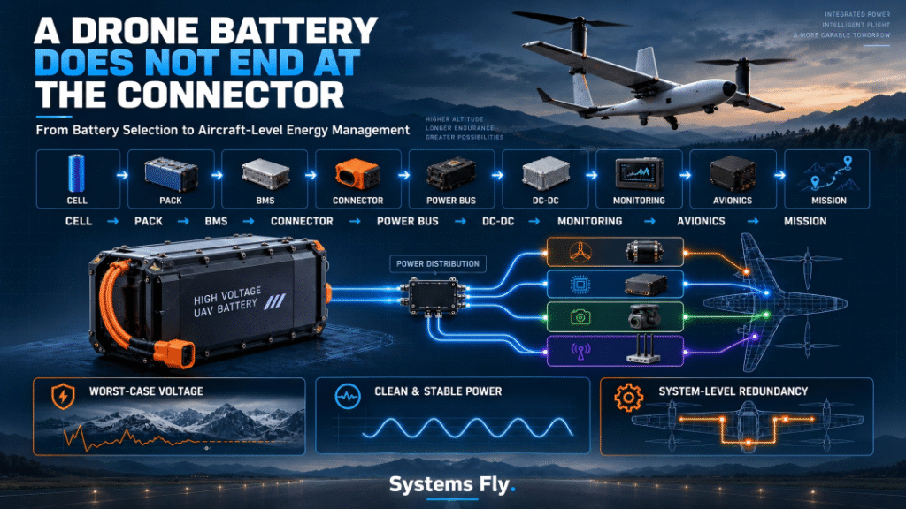
When people ask me about selecting a battery for an industrial drone, the conversation usually starts with familiar specifications:
How many cells in series?
How many amp-hours?
What energy density?
What continuous discharge rate?
What peak current?
How much does the battery weigh?
These are all important questions.
But from the perspective of a UAV battery engineer, I believe there is another question that is often asked too late:
How will the energy actually travel from the battery cells to every critical electronic system on the aircraft?
Because the battery does not directly power “the drone.”
It powers an entire electrical architecture.
Between the battery cells and the final loads sit:
BMS → Connectors → Cables → Power Distribution → DC-DC Conversion → Current Monitoring → Communication → Redundant Power Paths → Flight Controller / Payload / Avionics
And every one of those interfaces can affect flight reliability.
That is why I increasingly think about UAV batteries not as isolated products, but as the first stage of an aircraft-level power system.
1. A Battery Can Be Healthy While the Drone Still Suffers a Power Failure
Consider a hypothetical engineering scenario.
A fixed-wing UAV performs perfectly during ground testing.
Battery voltage looks normal.
Flight controller boots correctly.
Telemetry is stable.
Motors operate normally.
Then the aircraft climbs into a colder environment.
A DC-DC converter that appeared stable during room-temperature testing begins behaving differently under the combination of temperature, input voltage and load.
Ripple on the flight-controller supply increases.
The 5V rail temporarily falls outside the acceptable operating margin.
The MCU resets.
The aircraft loses control.
After the crash, someone may say:
“The flight controller failed.”
Someone else may suspect:
“The battery failed.”
But neither diagnosis captures the real problem.
The real problem was:
Power-system integration.
This distinction matters enormously.
A battery can have sufficient capacity and still be unsuitable for the aircraft.
A DC-DC converter can meet its nominal specification and still be unsuitable for the mission.
A flight controller can operate perfectly and still reset because the power delivered to it is unstable.
In UAV engineering, individual components do not fly.
Systems fly.
2. The Power Chain Starts at the Cell—but It Does Not End at the Pack
As a battery engineer, I naturally begin with the cell.
Cell chemistry and configuration determine fundamental characteristics such as:
- Voltage
- Capacity
- Internal resistance
- Maximum current
- Voltage sag
- Temperature behavior
- Energy density
Series configuration then determines the pack operating-voltage window.
For conventional lithium-ion/LiPo cells with approximately 3.7V nominal and 4.2V maximum voltage, moving from:
6S → 12S → 14S → 15S
dramatically changes the electrical environment seen by downstream components.
This is why selecting a DC-DC converter based only on:
“My battery is 44V.”
is dangerous.
A 12S battery is not simply a 44.4V source.
Its voltage changes continuously with:
- SOC
- Current
- Temperature
- Cell chemistry
- Internal resistance
- Aging
At full charge, a conventional 12S pack can reach approximately:
50.4V.
Under heavy load near low SOC, its terminal voltage can be substantially lower.
Therefore, downstream electronics must tolerate the entire operating envelope, not merely nominal voltage.
3. Battery Voltage Is Dynamic, Not Static
This is one of the most important ideas I try to communicate when discussing UAV battery systems.
Suppose the battery is:
12S 30Ah
Someone might write:
44.4V / 30Ah
on the specification sheet.
But the aircraft never experiences one fixed 44.4V condition.
During a real mission:
Takeoff → High current → Voltage sag
Cruise → Lower current → Voltage recovery
Climb → Current increases → Voltage drops
Payload activation → Transient load
Low SOC → Lower baseline voltage
Cold environment → Higher internal resistance → Greater sag
So the actual voltage supplied to the power electronics is constantly moving.
From a battery engineer’s perspective, therefore:
DC-DC input-range design must be based on the worst-case battery operating envelope—not the nominal battery voltage.
And that envelope should include margin.
4. The Battery Delivers “Raw Power”—Avionics Need Clean Power
The propulsion system can usually tolerate relatively wide battery-voltage variation.
Flight electronics cannot.
A UAV may contain loads requiring:
| Load | Typical Supply |
|---|---|
| Flight controller | 5V |
| Backup flight controller | 5V |
| Telemetry/data link | 5V / 12V |
| Companion computer | 5V / higher-power regulated rail |
| Camera | 12V |
| LiDAR | 12V / 24V |
| Gimbal | 12V / 24V |
| Navigation equipment | regulated low-noise power |
| Lighting/actuators | platform dependent |
The battery therefore provides energy, while the power-management system must transform that energy into the electrical conditions each subsystem requires.
This includes:
Voltage conversion
Voltage regulation
Filtering
Protection
Current measurement
Power distribution
Fault isolation
That is why I would describe the relationship this way:
The battery determines how much electrical energy is available. Power management determines whether that energy is usable.
5. Voltage Sag Is Where Battery Engineering Meets Avionics Engineering
This is one of the interfaces I find particularly important.
Imagine a heavy-lift multirotor during takeoff.
The motors demand a large current.
Battery current rises from:
40A → 120A
The battery has internal resistance.
Therefore, terminal voltage falls.
In simplified form:
V_load ≈ V_OCV − I × R_internal
As:
Current ↑
or:
Internal resistance ↑
voltage sag increases.
Now consider what happens downstream.
If the DC-DC converter has sufficient input margin:
Battery voltage falls → Converter maintains regulated output → Flight controller remains stable
But if the converter is operating close to its lower input boundary:
Battery voltage falls
↓
DC-DC regulation margin disappears
↓
5V output becomes unstable
↓
Flight controller / computer may reset
Suddenly, something that began as a battery impedance issue becomes an avionics failure.
6. This Is Why Battery Selection Cannot Stop at C-Rate
A battery specification might say:
10C continuous discharge
But that number alone tells me very little about whether the battery will work well in a specific aircraft.
I also want to understand:
- Actual pack DC internal resistance
- Voltage sag at mission current
- Temperature dependence
- Low-SOC power capability
- Cell consistency
- Connector resistance
- Cable losses
- Peak-current duration
- Pack thermal behavior
For industrial UAVs, a much more useful question is:
What voltage will actually reach the aircraft power bus under the worst expected mission condition?
That connects battery engineering directly with power-system engineering.
7. Current Monitoring Is Not Just a Battery Gauge
Many UAV operators think current monitoring exists mainly to calculate:
“How much battery is left?”
That is only one function.
Accurate current data can support at least three important tasks.
SOC Estimation
Coulomb counting integrates current over time:
Q_used = ∫ I(t)dt
The accuracy of the current sensor therefore directly affects accumulated capacity estimation.
Small errors can become significant over a long mission.
But there is a deeper application.
Power-System Diagnostics
Current behavior can reveal:
- Unexpected propulsion load
- Increasing mechanical resistance
- Abnormal payload consumption
- Connector problems
- Short circuits
- Motor/ESC abnormalities
And finally:
Battery Health Analysis
If we combine:
Current + Voltage + Temperature + SOC
we can begin to understand how the battery responds under load.
That creates useful information about:
- Internal resistance
- Power capability
- Aging
- Cell imbalance
- Abnormal degradation
So from my perspective, current monitoring is not simply instrumentation.
It is part of the battery-health and aircraft-health system.
8. SOC Alone Is Not Enough for Industrial UAVs
Suppose the flight controller reports:
SOC = 35%
Is the aircraft safe to continue the mission?
Not necessarily.
Imagine two identical battery packs.
Both show 35% SOC.
Battery A has low internal resistance.
Battery B is older and has significantly higher internal resistance.
During cruise, both may appear normal.
Then the aircraft needs maximum thrust.
Battery A maintains sufficient bus voltage.
Battery B experiences severe voltage sag.
Same SOC.
Completely different available power.
This is why I believe industrial UAV battery management should gradually move from:
“How much energy remains?”
toward:
“How much usable energy and power remain under the upcoming mission conditions?”
That is a much more meaningful definition of battery availability.
9. The Future BMS Should Understand the Mission
Traditional BMS logic focuses heavily on protection:
- Overvoltage
- Undervoltage
- Overcurrent
- Overtemperature
- Short circuit
- Cell balancing
These functions remain essential.
But for advanced industrial UAVs, the BMS can become much more useful.
Imagine the aircraft knows:
- Current SOC
- Battery SOH
- Cell temperatures
- Cell voltage spread
- Internal resistance
- Payload
- Expected climb
- Remaining distance
- Wind conditions
Instead of simply reporting:
Battery = 32%
the energy-management system could eventually answer:
This battery has enough usable power and energy to complete the remaining mission with the required reserve.
That is where battery data becomes operational intelligence.
10. Why CAN Becomes Increasingly Valuable
This also explains why communication architecture matters.
A simple analog current/voltage signal can work well on a small UAV.
But as aircraft become larger and more sophisticated, the power system may need to communicate:
- Pack voltage
- Current
- Power
- SOC
- SOH
- Temperature
- Cell alarms
- Fault codes
- Remaining capacity
- Available power
Now the power module is no longer simply a voltage converter.
It becomes a networked aircraft subsystem.
CAN is attractive in many industrial platforms because differential communication offers strong immunity to electrical noise and supports multi-node architectures.
A sophisticated system might look like:
Battery/BMS
↕
Power Management Module
↕
Flight Controller
↕
Companion Computer
↕
Telemetry / Ground Station
Now battery information can influence mission decisions.
That is much more powerful than simply displaying a voltage number.
11. But More Communication Does Not Automatically Mean Better Engineering
CAN is not automatically necessary for every UAV.
This is where system matching matters.
A small aircraft with:
- One flight controller
- One battery
- Minimal payload
- Short wiring
may perform perfectly well with analog voltage/current sensing.
I²C can also be useful for tightly integrated, short-distance board-level communication.
But as the aircraft becomes:
- Larger
- Higher power
- More distributed
- More electrically noisy
- More redundant
the advantages of CAN become increasingly valuable.
The correct architecture depends on the platform.
Engineering should never become:
“CAN is newer, therefore CAN is better.”
It should be:
“What communication architecture produces the required reliability at acceptable complexity, mass and cost?”
12. Multi-Rail Power Is Becoming More Important
A modern industrial UAV may simultaneously require:
5V + 12V + 24V + battery-bus voltage
This creates another integration challenge.
One approach is to install several independent DC-DC converters.
Technically, that can work.
But it introduces:
- More wiring
- More connectors
- More mass
- More thermal sources
- More failure points
- Potential EMI interactions
- More difficult troubleshooting
For larger aircraft, integrated multi-output power management can become attractive.
For example:
5V rail → Flight controller / companion computer
12V rail → Data link / camera / gimbal
24V rail → LiDAR / actuator / mission payload
The design objective is not merely convenience.
It is power-domain isolation.
13. A Payload Transient Should Not Reset the Flight Controller
Consider a gimbal connected to the same poorly designed power rail as the flight controller.
The gimbal starts rapidly.
Current spikes.
Bus voltage temporarily drops.
The flight controller resets.
The gimbal itself may be operating exactly as designed.
The battery may also be healthy.
But the power architecture allowed one non-critical load to disturb a flight-critical system.
That is a system-design failure.
A good power architecture should separate loads according to criticality.
For example:
Flight-Critical Domain
- Flight controller
- Navigation
- Essential communications
Mission Domain
- Camera
- LiDAR
- Gimbal
- Payload computer
High-Transient Domain
- Actuators
- Release mechanisms
- High-power accessories
Then one subsystem’s transient behavior is less likely to destabilize another.
14. From the Battery Side, Connectors and Cables Are Part of the Battery System
Battery discussions often end at the pack connector.
I don’t think they should.
At high current, every milliohm matters.
The basic relationship is:
P_loss = I²R
Suppose resistance across:
connector + cable + solder joint
is only:
5 mΩ
At 100A:
P_loss = 100² × 0.005 = 50W
That is 50 watts being converted into heat somewhere in the power path.
And because loss increases with the square of current, the problem becomes much more serious as UAV power rises.
This is why heavy-lift UAV battery engineering must consider:
- Connector contact resistance
- Cable cross-section
- Cable length
- Crimping
- Solder quality
- Contact aging
- Connector temperature
A battery pack with excellent cells can still perform badly through a poor electrical interface.
15. Higher System Voltage Can Reduce Current—and That Matters
This is one reason larger UAVs increasingly move toward higher-voltage battery architectures.
For the same electrical power:
P = V × I
If a propulsion system requires:
6 kW
At 25V:
I ≈ 240A
At 50V:
I ≈ 120A
At 100V:
I ≈ 60A
Higher voltage can reduce:
- Current
- Cable losses
- Connector heating
- Conductor mass
But it also introduces new challenges:
- Higher-voltage components
- Insulation requirements
- Creepage and clearance
- Switching-device selection
- Connector safety
- DC-DC input requirements
So again, there is no universally “best” voltage.
It is a system-level tradeoff.
16. Thermal Design Connects Everything
DC-DC conversion is not 100% efficient.
Neither are:
- Cables
- Connectors
- MOSFETs
- Current shunts
- Battery cells
Every loss eventually becomes heat.
For a DC-DC converter:
P_loss = P_out × (1/η − 1)
If a converter delivers 25W at 92% efficiency:
Input power is approximately:
27.2W
and roughly:
2.2W
must be dissipated as heat.
That may sound insignificant.
Inside a sealed UAV fuselage at high ambient temperature, however, several watts concentrated on a small PCB can become a serious thermal problem.
Now combine:
Battery heat + ESC heat + DC-DC heat + Computer heat + Solar heating
and thermal management becomes aircraft-level engineering.
17. Cold Temperature Creates the Opposite Problem
Battery engineers are particularly sensitive to cold environments.
As lithium battery temperature falls:
Internal resistance ↑
Voltage sag ↑
Available power ↓
At the same time, electronic components and converters may also behave differently.
So a power system that works perfectly during a 25°C bench test may behave differently at:
0°C
−10°C
or:
−20°C
This is why environmental testing matters.
The aircraft should not only be tested at:
Nominal voltage + Room temperature + Moderate load
It should also be evaluated under combinations such as:
Low SOC + Low temperature + Maximum power
and:
High temperature + Maximum continuous load
The worst condition is often a combination of variables—not one extreme parameter by itself.
18. Redundancy Changes Everything
For small recreational drones, a single battery and single power module may be acceptable.
For:
- Logistics UAVs
- Heavy-lift drones
- Long-range BVLOS aircraft
- Critical inspection platforms
- eVTOL
the consequences of power failure become much more serious.
Now we have to ask:
What happens if one battery fails?
What happens if one DC-DC converter fails?
What happens if one connector opens?
What happens if one power bus shorts?
This leads to redundancy.
19. Dual Batteries Are Not Automatically Redundant
This is another misconception.
Two batteries connected together do not automatically create a truly redundant system.
Suppose two packs are simply paralleled.
If one develops:
- Internal short circuit
- Abnormal voltage
- Connector failure
- Severe imbalance
the second battery may not necessarily isolate the fault.
True redundancy requires thinking about:
- Independent monitoring
- Reverse-current protection
- Fault isolation
- Switching logic
- Separate current paths
- Power-source priority
So I would distinguish:
More batteries
from:
Redundant power architecture.
They are not the same thing.
20. Flight-Control Power Deserves Its Own Safety Strategy
The propulsion system consumes most of the aircraft’s power.
But the flight controller consumes very little.
That creates an interesting opportunity.
Even if the main propulsion battery fails, a small independent backup battery may be able to keep:
- Flight controller
- Navigation
- Communication
- Critical electronics
alive for a period of time.
Depending on aircraft architecture, this could support:
- Fault reporting
- Controlled emergency procedures
- Parachute activation
- Data preservation
- Communication with the ground station
For critical aircraft, I believe it is useful to think about:
Propulsion Energy
and:
Avionics Survival Energy
as two related but different design problems.
21. Power Management Should Be Included in Battery Selection From Day One
When a UAV OEM sends me a battery requirement, I would ideally want more than:
12S / 30Ah / 10C / under 8 kg.
I would also want to understand:
- Motor configuration
- Maximum propulsion current
- Cruise current
- Peak-current duration
- Flight-controller voltage
- Payload voltages
- Companion-computer power
- Required communication interface
- Operating temperature
- Redundancy requirements
- Charging strategy
- Required flight time
Because those parameters determine whether we are really selecting:
a battery
or designing:
an energy system.
For industrial UAVs, it should increasingly be the second.
22. My Preferred Engineering Sequence
When discussing a new UAV power system, I would approach it roughly in this order:
Step 1 — Define the Mission
Payload, flight time, environment, altitude and duty cycle.
Step 2 — Define Propulsion Power
Cruise power, maximum continuous power and transient peak power.
Step 3 — Define Battery Architecture
Voltage, capacity, chemistry, energy density, discharge capability and thermal behavior.
Step 4 — Model the Worst-Case Bus Voltage
Especially:
Low SOC + Low temperature + High current + aged battery
Step 5 — Define All Power Rails
5V, 12V, 24V and raw battery bus.
Step 6 — Separate Critical and Non-Critical Loads
Do not allow payload transients to compromise flight control.
Step 7 — Define Monitoring
Voltage, current, temperature, SOC, SOH and fault states.
Step 8 — Define Communication
Analog, I²C, CAN or another architecture.
Step 9 — Define Redundancy
What can fail without losing the aircraft?
Step 10 — Validate the Whole System
Not just the battery.
Not just the converter.
Not just the flight controller.
The entire energy chain.
23. This Is Also Why “The Best Battery” Does Not Exist
Customers sometimes ask:
“What is your best UAV battery?”
My answer increasingly depends on the aircraft.
A high-energy-density battery may be ideal for long-range mapping.
A high-power battery may be better for heavy lift.
A long-cycle-life pack may make more economic sense for a training fleet.
A cold-temperature pack may be essential for winter inspection.
And the battery that looks best on paper may still be the wrong choice if its voltage behavior does not match the aircraft’s power electronics.
So instead of asking:
“Which battery has the best specifications?”
I prefer:
“Which battery and power architecture best match the mission?”
That is a fundamentally different engineering question.
24. The Industry Is Moving From Battery Monitoring to Energy Management
I believe this will become increasingly important as UAVs become larger and more autonomous.
The traditional model is:
Battery → Voltage/Current Sensor → Flight Controller
The future model may look more like:
Smart Battery / BMS
↓
Power Management System
↓
Flight Controller + Mission Computer
↓
Energy Prediction Algorithm
↓
Mission Planning
Now the aircraft does not simply know:
“Battery SOC = 42%.”
It understands:
“Given this battery’s SOH, temperature, internal resistance, payload, wind and remaining route, we have enough energy and power to complete the mission with a 25% safety reserve.”
That is a major shift.
From:
Battery Monitoring
to:
Energy-Aware Flight Management
25. Battery Data Could Eventually Become Part of Predictive Maintenance
There is another benefit.
If we continuously collect:
- Voltage
- Current
- Temperature
- Cycle count
- Voltage sag
- Cell imbalance
- Mission load
we can build a historical performance profile for each battery.
Instead of replacing a battery only when:
capacity < 80%
we may detect:
- Rising internal resistance
- Abnormal thermal behavior
- Increasing cell divergence
- Excessive voltage sag
- Reduced peak-power capability
before the pack becomes unsafe for the mission.
For commercial drone fleets, this could be much more valuable than a simple cycle counter.
26. The Real KPI May Eventually Be “Available Mission Energy”
Battery specifications normally describe:
Nominal Energy = Voltage × Capacity
But not all nominal energy is operationally usable.
A more realistic conceptual model might be:
Available Mission Energy
=
Nominal Energy
− Low-SOC Reserve
− Temperature Derating
− Aging Derating
− Voltage-Sag Limitation
− Safety Reserve
And even that is not enough.
The battery must also satisfy:
Available Power ≥ Required Mission Power
So a UAV battery has two simultaneous obligations:
Enough energy to finish the mission
and:
Enough power to survive the hardest moment of the mission.
This is why Wh/kg and C-rate should never be evaluated independently.
27. From Battery Supplier to Energy-System Partner
This is also changing how I think about the role of a UAV battery supplier.
The traditional supplier model is:
Customer provides voltage and capacity → Supplier provides battery.
But industrial UAV projects increasingly require deeper collaboration.
The discussion may need to include:
Cell selection
↓
Pack architecture
↓
BMS
↓
Connector and cable
↓
Power management
↓
Charging strategy
↓
Flight-data feedback
↓
Battery lifecycle management
For complex industrial UAVs, especially heavy-lift, logistics, long-range and eVTOL platforms, this systems approach can create much more value than simply supplying a battery pack.
Final Thoughts: A Drone Battery Does Not End at the Connector
As a UAV battery engineer, this is probably the most important point I would like aircraft designers to remember:
The battery does not end at the battery connector.
Its behavior continues through the entire aircraft.
Battery internal resistance influences:
Voltage sag.
Voltage sag influences:
DC-DC operating margin.
DC-DC stability influences:
Avionics power quality.
Power quality influences:
Flight-control reliability.
Current measurement influences:
SOC estimation and fault detection.
Communication influences:
How intelligently the aircraft can use battery information.
Thermal design influences:
Reliability.
Redundancy influences:
Whether one failure becomes an aircraft loss.
So the engineering chain is not simply:
Battery → Drone
It is:
Cell → Pack → BMS → Connector → Power Bus → DC-DC → Monitoring → Avionics → Mission
And every interface matters.
This is why I believe the next generation of industrial UAV battery engineering should move beyond:
“How many volts, amp-hours and C-rate do you need?”
toward a much more useful question:
“What power and energy architecture does this aircraft need to complete its mission safely and repeatedly?”
Because ultimately, the best UAV battery is not the one with the most impressive datasheet.
It is the one that works correctly with the aircraft—
from takeoff to landing, from full charge to low SOC, from hot ground conditions to cold altitude, and from the first flight to the end of its useful life.
#DroneBattery #UAV #BatteryEngineering #PowerManagement #BMS #DroneTechnology #IndustrialDrones #UAVEngineering #PowerElectronics #DCDC #EnergyManagement #BatteryTechnology #FlightSafety #HeavyLiftDrone #DroneDesign #EVTOL #AutonomousSystems #PredictiveMaintenance